The SOLIDWORKS Defeature tool is a technique that can be used to simplify assembly components, as it enables you to remove details from a part of an assembly.
Defeature tool is a
technique that can be used to simplify assembly components, as it enables you
to remove details from a part of an assembly. You can save the less-detailed
model to a separate file and maintain references to the original part or
assembly. Defeature helps reduce file size to improve performance with large
models. The new file has the same mass and centre of gravity as assigned mass
properties. This tool is often used to remove proprietary information you would
not like others to see and share files without revealing all the design details
of the model. This in turn will also speed up your open/rebuild times.
Defeature functionality includes
the ability to:
- Remove
internal detail in a design
- Remove small
features below a user-defined value
- Preserve
necessary functional holes and features
- Maintain
relative motion between parts without the internal details
- Save your
assembly as a single part
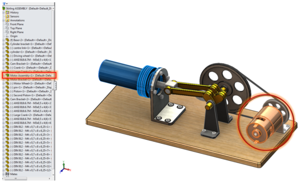
The image below is a Stirling
engine assembly that contains a subassembly where the Defeature tool can be
used.

Open the subassembly and you can
see that the motor sub assembly consists of 4 parts that are mated in place.


The defeature tool is under
Tool > Defeature

The image below shows the
first screen of the Defeature tool and the selection for this assembly.

1.
Internal Components: This selection allows Defeature
to remove any internal component that is inside your assembly.
2.
Small Components: This selection will allow you
to specify a percentage and any component that is smaller than that percentage
will be removed.
3.
Display: This option will allow you to see all the
components, which components are being removed, or which components are left
behind.
4.
Exceptions: Components selected in this box will not be
removed.
5.
Section View: This option enables you to
temporally section the assembly to help see the inside of our assembly and
select certain components.
6. Next: Moves to the next screen of the
Defeature tool.

The second screen of the
Defeature tool enable you to create a group of componments that have no
movement between them and it enables you to list out any mates that Defeature assumes you will want to
maintain between your groups.
Motion is not required for
this subassembly. Click Next
The
image below shows the the third screen of the Defeaure tool which enables you
to keep any specific features in the model. For this model I have select the
the two holes highlighted to keep as the are used in the main stirling engine
assemble to mate the motor in place.

1. Features
to Keep: This
box will allow you to keep features that are important to your model. (In this
example, the selected holes)
2. Select All Holes: All the holes in the assembly/part will be
selected to be removed.
3.
Select
holes between: You
can determine a size range to determine which holes are removed.
The next
screen will bring up a will show you the final comparison between the
original model and the Defeature version. Notice the Defeature model many
features have been removed and the simplified version is now a part file.

Select the ‘save the file as a separate file’ and when
you hit the tick, it will open the
window shown below and ask you to save the simplified model.

We can now use the ‘Defeature’ part to replace the motor
assembly, so right click on the assembly and you can select ‘replace
components’

Select the Defeature part and select the appropriate mates.
The holes that were excluded in the Defeature tool are now used to mate the part to the assembly.


The image below shows the motor subassembly has been
replaced with the Defeature part.

Using the AssemblyXpert, you can see the effect
this has had on the rebuild time of the Stirling engine assembly. There is a
decrease in the rebuild/ loading time.


Before After
Bismaya Sabu
Applications Engineer